Thursday, November 17, 2016

Tertiary winding in Power Transformer


The Tertiary winding with DELTA connection is normally used in Yy connection power & Auto transformers for following purpose.

1. The Tertiary winding used as a path for the Zero sequence current  during secondary loaded with unbalanced load. Normally the primary neutral point would not be connected with system  ground. Tertiary winding one DELTA point is connected with system ground which is prevent the shifting of secondary neutral point and  the voltages become unsymmetrical during unbalanced load condition. Other wise the zero sequence current will flow through the secondary neutral connected with Transformer Tank and tank will get heat up.

2. When an external Earth Fault occurs, the resulting zero sequence currents  flow through the OPEN DELTA winding to ground.This prevents the zero sequence currents from flowing through the Transformer. This also prevents abnormal DIFFERENTIAL RELAY operation of the Transformer for external faults.

3. Some times a external resistor is used in the path of Delta to ground connection to limit the Current circulation. 

4. Some times this winding is used as a station supply and surge arrester are used to prevent the surges from the load side. 

Protection Arrangement

The CT in the closed conductor will detect asymmetrical-faults such as turn-to-turn, or winding-to-winding and connected with instantaneous over current 51 and other and one core is connected with winding Temperature meter.

The CT in the Grounding conductor will detect ground-faults in the delta winding. 


Tuesday, August 16, 2016

GIS SURGE ARRESTER TESTING

1. GIS surge arrester was tested by injecting nominal voltage injection during HV test 

2.In 380 kV GIS the single phase nominal voltage 220kV was injected in Surge Arrester Through bus.

3. The leakage current mili amps measurement was measured in surge counter and Multi meter.

4. There by the paper connections are conformed.

5. Some cause the outgoing cable bus link and Surge arrester link will be same. So arrester should dismantle separately and Tan Delta test should contact on the table.


Saturday, August 6, 2016

REC 670 Minimum Current Measurement Issue

1. 380 kV line  Metering CT was connected with BCU ( Bay control Unit) in GIS LCC.

2. The metering CT Ratio is 1500/1.

3. During SAS Pre commissioning measurement was checked like current injected 5% , 10% , 50%.

4. 5% Primary current 75 amps and REC 670 not read and current shows 0 in the display.

5. The secondary of 75 Amps is 0.05 amps which is not seance  by REC 670 relay.

6. MW also shows zero because of current seances as 0.

7. REC 670 seance above 100 amps primary that means above 0.061 amps.

8. Client not accept this condition.

9. After long discusses the Relay setting was change as below and relay start to read from Zero current.

10. This setting was changed for Reactive and Active & Apparent Power


Wednesday, August 3, 2016

ELSTER ENERGY METER TESTING PROB


RED 670 SAS PRB ISSUE


As per drawing there are two SAS IED 61850 port should be available in the relay. One is main port and other one is redundant port.


But the relay dose n't have the redundant port.

The new card was ordered with PRP redundant port.


The new card was changed but both port was not communicated with SAS and relay shows following error.


Relay was not communicate with SAS . 

Manufacturer send a firmware for the new card. The firm ware is a " . bat" each relay have  individual firmware. 

Initially this firm ware not up load in to relay and its need to switch off fire wall and Auti vireos.

Then firmware was updated in the relay and Redundant PRP status shows " OK". 


 Still relay not communicate with SAS and shows following error.


Then SAS engineer check the IP address in the relay and it was not mach.

Finally he correct IP address and every think get normal and relay communicated with SAS.


Wednesday, July 27, 2016

Winding Resistance Issue in 67 MVA Transformer

The winding resistance Measurement of the Transformer  most impotent  test because

1. To find out the week part and break down in the winding
2. To find out the Bolt tightness and connection shoes gripping

Normally winding resistance measured between

1. Phase to Phase in Delta & Star connection

RY , YB, BR

2. Phase to neutral in  Star connection

RN, YN, BN

This site test result will be compared with factory test result and the error should be less than ≤ 5%

Issue in site Test Result

Transformer Rating

67 MVA ,

115/13.8 kV

Dyn1 three winding Transformer


During site test the LV side winding resistance as below


PHASE SITE RESULT  AT 30⁰ C SITE RESULT  AT 75⁰  FAT RESULT  AT 75⁰ C ERROR
RN 6.599 m 7.577 m 6.872 m ≥ 10%
YN 5.788 mΩ 6.646 mΩ 6.674 mΩ ≤ 5%
BN 5.752 mΩ 6.604 mΩ 6.6322 mΩ ≤ 5%
RY 12.18 m 13.99 m 13.36 m ≤ 5%
YB 11.38 mΩ 13.07 mΩ 13.125 mΩ ≥ 10%
BR 12.19 mΩ 13.99 mΩ 13.323 mΩ ≤ 5%


As per site test result R phase winding resistance is high.

The result was sent to factory and factory suggested to clean the surface and meassure value again with 10 DC volt.

The Transformer winding resistance again measured with Omicron CPC 100 . 
The inject current ratings of the kit are 2A, 6A, 400A.
So 6A was injected for measurement and the results are same.

Measured value 7.577 mΩ   at 75 ⁰c and FAT value 6.874 mΩ   at 75 ⁰c error value is -10% and it should be ≤ -5%. ( Test report attached )

Manufacturer suggested 10A dc but in equipment there is no option for that value.

The winding resistance will not vary with injected current. 

Because winding resistance is very low in terms of  mΩ. 

Minimum current is enough for measure the resistance.  2A current was injected and result was same. 

But minimum current will take more time to stable the  reading (resistance value).


Problem Analysis and Rectification


Factory testing engineers came to site.


Factory Action -1 


Factory Action - 2


After complete all rectification process winding resistance was measured and  result found was with in the limit. 5.533m ohms


Tuesday, July 26, 2016

RED 670 Differential current


There is a issue raised during differential stability in End to End test.


1. 1 1/2 scheme there are two CTs are connected in RED 670 relay

2. 1 amps with 0 dec injected in one CT and 1 amps with 180 dec injected in other CT

3. Now the Differential current IDL1MAG ,  IDL2MAG , IDL3MAG in three phase should be zero.

4. But there is small primary current read in all three phases around 100Amps in both  source end and remote end relays.

5. Engineers tried to solve but not.

6. Then the line was energized and differential current got normal around zero.

Differential reading after energize the line


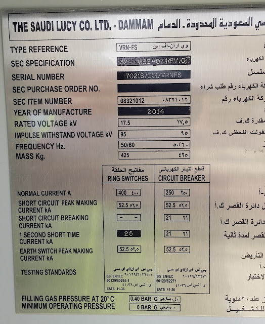
Distribution RMU


Ring Main Unit used as a junction to provided reliable supply for Station Transformer. SST connected with two different incomer supplies. One is coming from out side distribution supply and other one is coming from station distribution 13.8 kV feeder through RMU.


At the same time Station distribution supply can take for out side distribution through RMU.


RMU 


Relay Setting 


CT connections


Back side cable cover interlock with Earth Switch


RMU -2 


About Me

My photo
THIS IS SIVA T&C ENGINEER IN NCC LTD - SAUDI.