Monday, December 9, 2013

High Impedance Busbar protection CT connections


One and half scheme High Impedance Busbar protection -1

This is normal One and half scheme  bus bar protection.
1A and 1B bus bar scheme will operate separately irrespective of middle breaker or DS close or open. In this scheme the middle breaker CTs are over lapped to protect the middle breaker. Consider the 1A side breaker CT connected with 1A bus scheme and  1B side breaker CT connected with 1B bus scheme. If any fault in middle breaker it will consider as the out zone fault for both protection schemes. So the breaker is proteded by overlapping the CTs. The Disconnecter Switch (DS) contact is no need in the CT secondary circuit as like Double bus scheme.


One and half scheme High Impedance Busbar protection -2

This circuit special one and there is no middle breaker and CT. The middle DS is separate the 1A &1B bus.

There is no separate incoming  line for 1B bus and energaized through  1A bus only.

There are two condition for protection operation


1. When middle DS closed , both relay will coming into picture. Both 1A & 1B Relay will operate for fault in any bus. A disconnector 'NC' contact will open one CT earth point to maintain the single point earthing.

2. When middle DS open, 1B relay will be disconnected from the circuit and a disconnector 'NO' contact will open the CT secondary circuit in 1B side to avoid the relay operation for 1A bus fault.


Double Bus High Impedance Busbar protection -3


The CT secondary current will select the relay by DS contacts status.

1. When 1A DS closed and current will go to 1A relay through Early make and Late break  1A DS contact. If 1B DS closed current will go to 1B relay through Early make and Late break 1B DS contact.

2. If  both DS are closed and current will go to both relays. If both DS are open CT will shorted through DS 'NC' contacts.

3. During fault condition trip also selected through DS contacts to trip the particular breakers connected in faulty bus.


Tuesday, November 5, 2013

RED 670 FAIL

There are two 380 KV  line in the substation and both are continuously charged for three months with 70% load in summer. The load was reduced in winter and one line got shutdown. The differential relay RED 670 which is belong to shutdown get started to restart again and again and finally its comes a stage as below

NORMAL RELAY MAIN MENU 


DEFECTIVE  RELAY MAIN MENU 


1. There is no Measurement column and instant of 'RED670' , ' IED 6x0.1.0  in the top line
2. There is no previous disturbance records and Events
3. There is no inbuilt serial numbers and type
4. Ready LED glows


1. All final relay settings are corrupted there is no more data


ABB suggested the following

1. DC switch ON/OFF

But nothing will happened same status

2. Up load final relay setting files again
Already rear side fiber communication with SAS failed and laptop connected in front port and relay was communicated. But setting file can't write and read from relay.

Finally ABB come to site and find out the problem. The Central processing unit ( CPU ) cord  got failure and changed new one. Setting files are uploaded and tested. Now relay works fine.


SUBSTATION COMMUNICATION SYSTEM BASIC

The communication between station to station established by a separate communication system.


OPTICAL GROUND WIRE ( OPGW )

An OPGW cable contains a tubular structure with one or more optical fiber in it, surrounded by layers of steel and and aluminium wires. The OPGW cable is run between the tops of high-voltage Towers. The conductive part of the cable serves to bond adjacent towers to earth ground, and shields the high voltage conductors from lightning strikes. The optical fibers within the cable can be used for high-speed transmission of data for protection and control and utility's own voice and data communication.


U/G NMFOC

OPGW cable will bring to bottom of the tower and spliced with Single mode Under Ground Non Metallic Fiber Optic cable in a junction box. NMFOC cable made connection between OPGW and OFMR , ( in side substation communication room ) laying through the under ground communication duct bank.
Its may be 48 core, 24 core 12 core depend upon requirement.


OPTICAL FIBER MANAGEMENT RACK  (OFMR )

OFMR is a junction box to connect the NMFOC to other communication equipment. OFMR mounted in the Fiber Splicing / Termination Panel (FSTP). OFMR suitable for terminate 48 ,24 ,12 core  U/G NMFOC. Small length Pigtail fiber cable is used to connect the NMFOC and OFMR.


OFMR - MFDC


PATCH CABLE SPECIFICATION  FC/ PC Type connector in one end (ITU-T-G655)
PIGTAIL CABLE SPECIFICATION FC/PC Type connector in one end ( ITU-T- G655)


FSTP


SYNCHRONOUS DIGITAL HIERARCHY ( SDH )

SDH is the total communication unit used to convert and invert the electrical signal  and voice signals to digital signal. SDH is a unit of equipments contain Converts and Digital Cross connection Panel ( DCX ), Data Voice Multiplexer ( DVM ). DVM panels are contain number of channels with FOX 515. Each chenals are specified for each purposes Protection , SCADA , Voice communication. FOX 515 connected with MDF ( Main Distribution Frame ) by useing 100 pair cable.


COMMUNICATION RACK


JUNCTION CONNECTION 


DXC & DVM PANELS


MAIN DISTRIBUTION FRAME ( MDF)

MDF is a signal disribution rack to connect the electrical signal wires from Protection panels and SCADA , Telephone panels.


Thursday, September 5, 2013

SO2 MEASUREMENT IN SF6 GAS


The concentration of SO2 is an indicator for the presence of decomposition products in SF6 gas. The SO2 measurement in SF6 gas in the GIS equipment which is energized condition is easy way to analyze the abnormalities.


Gastec Detector Tubes


Gastec Tube


Gastec Detector Tubes are used for the rapid measurement of SO2 in SF6 gas. These Pre-calibrated, direct-read detector tubes offer distinct lines of demarcation for easier viewing and color charts. Each tube contains detecting reagents that are especially sensitive to the target substance and quickly produces a distinct layer color change. 

Gastec Gas Sampling Pumps


Gastec Gas Sampling Pumps are used to take the sample of SF6 gasCollect the SF6 gas in a polythene bag from the equipment Non returnable value. Take a fresh Detector Tubes and broke two edges and fix one edge with Gas sampling pump, insert the other end  in to gas collected polythene bag. Then pull the gas Pump handle.  Now gas will accumulated in the gas tube. If SO2 presence in the SF6 gas, the tube in side Blue color will be change in to Yellow. 


Monday, September 2, 2013

HYUNDAI 380KV CB PROBLEMS


Problem -1

A Circuit Breaker opened from the remote end for some outage work . After complete the work breaker was tried to close again, but "R" phase CB pole not closed and other two poles are closed . 
Immediately Pole Discrepancy Stage -1 operated and closed breaker poles are opened. 

CB was taken outage for further investigation.

1.+ve & -ve is checked across contact K1 - ok.
2. Individual coil resistance - ok
3. Function of K1 checked - ok
4. CB was closed by manually press the closing coil nob. Again locally CB was tried to close. All three phases are closed. We thought there is struck up in the close coil nob. So again CB tried to close but this time same problem happened.   


5. Resistance checked between point A & B 
R- Phase = 90 ohms Y= 40 ohms B= 40 ohms

The resistance R1 not shown in the drawing . So we desired wire problem between coil and point 'A'. Then the R1 was found between between coil and point 'A'. 

A wire connected in the resistance was found disconnected. And circuit taken full resistance value. So the enough current was not flowing through the coil to pickup. 


Problem -2

When close the CB ,  " R" Pole oil pressure comes to "0" point. Pole was not closed. Same PD- Stage 1 operated and other poles are tripped.

After long investigation found the closing coil nob is in middle position. So when ever close comment came total compressed pressure was relished thorough a valve. Then oil pressurizing  motor automatically ON but oil pressure was not increased.

 Then closing coil nob was properly pulled out. Oil pressure was increased by manually up 10Mpa. Then motor was ON and pressure got normal.


The same problem will happened if CB close with "0" pressure. 


Tuesday, August 20, 2013

FERRORESONANCE IN VOLTAGE TRANSFORMER

Ferroresonance is a phenomena appears in the system voltage in the non linear Inductance circuit , capacitance load circuit after following transient disturbances.

Transient over voltage in the system (Variable Voltage in the system)
Lighting over voltage  in the system
Temporary fault or switching operation of CB , DS or fault clearing
Transformer energization.

The voltage jump from one stable state to another ( Oscillation ) is highly depend on initial conditions of the above mention circuit. ( residual flux in the transformer or non linear load , capacitance, switching instant  ).

The effect of the Ferroresonance is,

1.Sustained Over voltage and Over current with waveform distortion,
2.Loud noise,
3. Malfunction of protection relays,
4.Over heating
5.Electrical equipment damage,
6.Insulation breakdown.

Once the Ferroresonance has appeared, the system keeps working under Ferroresonance situation until the source fail to give the energy to maintain it.


FERRORESONANCE IN VOLTAGE TRANSFORMER

 Voltage transformers are devices particularly prone to ferroresonance on account of its nonlinear character and operating characteristics, because they are designed to work under conditions similar to no-load ones.
On the one hand, inductive voltage transformers are even more susceptible to ferroresonance, since they have a higher inductive character and, consequently, they need a lower capacitance to form the ferroresonant circuit . This tendency of inductive transformers to be prone to ferroresonance becomes more important when operating in isolated grounded systems or when feeded by circuits that include circuit breakers with grading capacitances. On the other hand, the design of capacitive voltage transformers includes a capacitive divider that increases their tendency to ferroresonance occurrence.

The controlling of ferroresonance in primary side is very difficult since the controlling of causes of ferroresonance. But   ferroresonance effect can control in VT secondary voltage and can avoid the damaging the secondary equipments ( meters, relays) malfunctions of protective relays .

1. Inductive Voltage Transformers 

 To control these  ferroresonance oscillations , a damping circuit is insert in the transformer’s
open-delta secondary (tertiary) winding.


Damping circuit in the transformer’s open-delta secondary
(tertiary) winding

A damping circuit formed by a resistor connected in series with an LC filter or a saturable inductor.
The performance of LC filters is used to damp the ferroresonant oscillation at frequencies different from the
fundamental one.


Basic circuits for ferroresonance suppression


In this circuit the resistor is continiously connected in in the seconday circuit and more heat take places. And the other hand , the use of a saturable inductor connected in series with a resistor makes the damping circuit adequate for every ferroresonant oscillation, since its performance with regard to saturation does not depend on the frequency content. This way, the inductor works as a magnetic switch: when the ferroresonant phenomenon appears, the inductor gets saturated, giving way to the reduction of its impedance and inserting the series-connected resistor that allows damping the ferroresonance.


3.2. Capacitive Voltage Transformers


These kinds of transformers usually include a ferroresonance suppression system . Althoughthe aim of this system is to damp effectively the ferroresonance phenomenon, its inclusion may affect considerably the transient response of the transformer, causing misoperation of protective relays and associated systems.
Nowadays, there are mainly two types of ferroresonance suppression circuits in capacitive voltage transformers:
Active Ferroresonance Suppression Circuits (AFSC), base on a series-parallel RLC filter, and Passive Ferroresonance Suppression Circuits (PFSC), based on a saturable inductor in series with a damping resistance. AFSC are more effective in damping the ferroresonant oscillations than PFSC, although its influence on the transient response of the transformer is higher. Both systems usually incorporate surge protection devices. Figure shows the typical elements included in the design of a ferroresonance suppression circuit.

More details about Ferroresonance  in Voltage Transformer  DOWNLOAD

Thursday, August 15, 2013

LINE EARTH SWITCH INTERLOCK


1.The line energization will causes damage if other end Line earth switch was closed. 
The remote end earth switch interlock scheme is used to avoid this condition.

2. Sub-1 line Earth Switch status given to Sub-2  line DS  interlock and Sub-2 line Earth Switch status given to Sub-1 Dis connector interlock.

3.If Sub-1 ES closed then Sub-2 line DS should not close vic var. Same Sub-2 ES closed Sub-1 line DS should not close vic var.

4. Take  ES status 'NO' contact  and transfer to remote end trough protection communication equipment. Pick up one Aux. Relay and relay contact add with DS interlock.

5. Same way take  DS status 'NO' contact and transfer to remote end trough protection communication equipment. Pick up one Aux. Relay and relay contact add with ES interlock.

6.Two communication channels are required to send and receive the DS, ES status.


CT PRIMARY INJECTION ISSUES


1. Short all Spare CT secondary cores in Primary current injection path. Otherwise heavy voltage will develop in the  Spare core and damage CT secondary.

2. Check any open path in the used secondary taps and tightness of all CT circuit. Any sound hearing in the CT then consider open circuit in the secondary.

3. If any CT cores are open then the equipment will not drive the Primary current more than 50 A.

4. Check the Primary current injection Equipment Auxiliary Supply cable. It should withstand more than 20A continuous rating.

5. Use separate generator supply for Primary current injection test. Otherwise the Primary current wouldn't constant value. 

Wednesday, August 14, 2013

SUBSTATION AUTOMATION SYSTEM (SAS)


Nowadays the substations are upgraded with SAS and substations become unmanned.

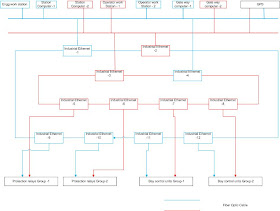
SAS is the internal Network made inside the Substation. All Protection relays and Bay control units are connected in that network through Industrial Ethernet . This network is controlled and monitor by Station master computers and also this network connected with Station Operator PCs, Station Engineering PCs, GATE WAY computers to control and monitor the substation activities from remote end by SCADA system.

Network

First the network is made section vice according to voltage level. For example all 380kv all protection Relays and Bay control units are connected consider as one group and its connected with two network.
One is main and other one is backup. All relays and BCUs are connected with Industrial Ethernet Switch with fiber optic cable. All Ethernet switches are connected each other in the network.


There are two net work formed for each voltage level . One is main and other one is standby. First network is connected with Station level computer -1 , Gate way computer -1 , Operator work station -1,Engg Station computer , and GPS. Second network is connected  Station level computer -2 , Operator work station -2, Gate way computer -2 and GPS.

Protection relays 

All numerical relays can connect with SAS network through fiber optic connection. Set-1 Relays ( ABB relays) are grouped for one Ethernet and backup SET-2 relays ( AREVA relays ) are grouped in other Ethernet. All relays should have two fiber connections, one is main and other one is back up ( REDUNDANT PRP).

Non numerical relays are connected with SAS network through RTU.


Bay control units


Bay Control Units is Numerical relay. Fixed in GIS bay Local control panel ( LCC ) .
BCUs are used for Bay equipment operations, Monitor the bay events and Measurement monitor.

a. Bay equipment operations

Bay equipment CB, Disconnectors , Earth switches can Open close according to its Soft and hard wire logic.

Soft logic made inside the BCU. So all open & close status of all equipments in the particular bay  should give to BCU. For example to close the breaker in double bus scheme in service condition needs DS status. and for close the DS  needs ES status.

Each and every bays can share the status each other through GOOSE signal. This status can monitor in SCADA and SOE.

b. Measurement Monitor

CT,VT inputs can connect with BCU for Current and Voltage monitoring and Synchro Check.


For double bus scheme Bus voltage and line voltage should given to BCU for synchro check function
All voltage related to the bus should give to BCU.

Station master computers


Station master computer is loaded with SAS software Ex.Micro SCADA - ABB.  This software is used to connect all IEDs ( Relays ) BCUs and make a way to communicate each other.

SAS engineers download all configuration files from all protection Relays.

ABB relays - PCM -I file for individual relays or PCM - P file for all relays in one project. ( No need          *. ICD files)

AREVA relays - *.PLC file ( No need *.SCT file for SAS configuration)

Siemens relays - Device file ( No need Variant file)

SAS engineers will add ( Engineering ) the SAS communication function block in that configurations.All function block in the relay configuration will connected with SAS communication function block. Now this file is called System Configuration Description file ( SCD file).

This SCD files again will uploaded in all protection relays.

Micro SCADA will communicate the relays through this SAS communication function block and get the all Status, Events and voltage current measurement of the relays.

This Events displayed as Alarm list,Event List in the Operator work station PC.


Protection relays can't triggered by using Micro SCADA.

BCUs and Auto Re close RTCC relays configurations allows to receive the command from SAS.


BCUs - Open / Close command

Auto Re close - IN / OUT command
RTCC - Rise / Lower 


Station Operator PCs

Station Operator PCs are connected with SAS network for Station equipment operations. The Micro SCADA allows Station operators to Open and Close the  Station equipments and monitors Events, Alarms, Measurements through this PC.


Station Engineering PCs

 Station Engineering PCs are connected with SAS network for Station Protection relays communications. The Micro SCADA allows Station operators to Monitor and upload and download the relay configurations.


GATE WAY computers

Station Engineering PCs are connected with SAS network for substation remote Remote access. The Micro SCADA allows Station operators to Open and Close the  Station equipments and monitors Events, Alarms, Measurements through this PC in Remote places. SCADA and SOE points are send to NCC through gate way.

RTU ( Remote Terminal Unit)

All non numerical relays are communicating with SAS network through RTU.


SAS Photos