Substation Testing and Commissioning

Tuesday, July 21, 2020

MICOM 546 End to End ISSUE

MICOM 546 End to End ISSUE


ISSUE 

During end to end test,  Micom P546 has issue related to differential stability. Below is the concerned issue:

·   Both the CH-1 and CH-2 are being used for differential communication, dual redundant. While injecting stable current from both ends through GPS, 

       1.When CH-1 is removed from either end, Qurayyah or Doha, the differential remains stable and the relay gives no tripping. The channel is then connected back and differential comm. fail alarm goes. 

       2. Then same is done for CH-2. There is no issue with this test.

·     3.  Once both CH-1 and CH-2 are removed, and any one channel is connected back, either CH-1 or CH-2, the Doha side relay gives differential trip for an instant and then gets back to normal i.e. stable. It should not behave in this manner and give no trip. The Qurayyah side relay gives no trip, which is correct behavior.
·        
      4. When Qurayyah side relay DC is turned off and made on again, it gives differential trip at Doha side relay. Not the expected behavior. It should not give any trip. But when Doha side relay is made of and on again, then there is no trip at any side.

·       5.  Sometimes CH-1 signal lost signal is coming as 1 and going 0 in measurement-4. CH-2 has no lost signal. But when both channels have no signal lost, that time also same problem is being faced.

·         
      6. The differential communication is through DVM (fox 515, Optif card). 

7. This all is happening if the setting is set to ‘Dual Redundant’ in Prot. Comm/Im64 at both ends. If the setting is set to ‘2 Terminal’ at both ends, then CH-2 becomes unavailable and relay differential function works on CH-1 only. With this CH-1, relay is behaving normal as it should work. 

8. There is 1 CT (Single Breaker)at Qurayyah side and 2 CT’s (1 and a half breaker scheme) at Doha side.


Analyzation 

1. Check the fiber optic cable loss and it should be -22 to -24 db . Otherwise attenuator should add to reduce 

2. Configuration and setting file send to GE and they decided to upgrade the firmware . GE Engineer come to site and updated the latest firmware both side of relay 

3. But issue not solved. 


4. Finally We put  a setup of 2 relays (Micom P546) at Doha side directly connected through fiber cable with each other to confirm that the issue is not related with communication. When test was done, we faced the same issue of differential stability which was coming before.


5. This confirmed us that there is some issue in relay configuration (PSL) and not communication or setting file of the relay. Therefore, we put a PSL file of another relay (from another station) and configured it with input and outputs as per our scheme for both end relays. This made the relays work fine at both ends.

6.It should be made clear that the existing PSL file at DOHA was in use (energised) and the relay was being used as Stub Protection. On existing PSL, SAS was configured from before. Open loop and close loop were done 100% from before. Now all SAS activity will be revised as well.

7. At Qurayyah End, the default PSL file was used for final setting but had the same problem. So another station relay PSL file was written to it and its working fine now.  

8.We compared the existing PSL with another station PSL but couldn’t find any difference. This is strange.

9.Now the issue has been solved and checked through injection from both ends.

Tuesday, August 6, 2019

OUTAGE WRIT UP


OUTAGE WRIT UP 

  1. Read the PTS  

a.       Scope of work
b.       Number of panels
c.        Additional card for SCADA, SOE, Annu, DFR

  1. Site Visit
1.       Collect all IFC drawings from existing station
2.       Collect all existing  point list
3.       Check cable rote length for fiber & control cables & Power cables

  1. Materials
1.       Check the availability of all Control & Power & Fiber optic  cables and cable hose
2.       Check Ferule Machine and tap
3.       Check Lugs
4.       Check panels and find the missing materials before outage
5.       Check the loose materials
6.       Check all communication materials ( Optif , SFT ect)

  1. Point list
              SAS, SACDA, SOE, Annu, DFR

1.       Check all New point list IFC
2.       Before Outage, discuss with SCADA deportment for using the spare points through PMD
3.       Submit the RFI and Point list to SCDA deportment soft & Hard copy and conform the witness.
4.       Check SAS engineer Iquma & He should be direct employ of the company otherwise SAS Vendor should give the letter with proper note pad and stamp ( Strict order from SCADA deportment ) .
5.       Don’t do existing Measurement points, Transducer will make issue.
6.       After open loop submit the points to SCADA & PCC for SAS close loop or SCADA final commissioning
7.       Conform the PCC witness & SCADA witness & SCADA vendor for final commissioning.

  1. Vendor follow ups

1.       Check the PO for all Vendors
2.       Send mail for vendors SAS , SCADA, SOE, DFR and Fault locator , AMI , Fiber optic testing team.
3.       Check SEC ID
4.       Collect Iqama copy from vendor
5.       Collect all PO copies for Temporary access.
6.       Collect laptop details for Temporary access.

  1.  Testing activities
1.        Don’t touch the Protection panels without getting permission from PCC
2.       Whenever touch existing panel inform PED.
3.       Testing agency engineer SEC ID , Testing Approval
4.        Testing Team - Panel wiring , Relay configuration, Aux relays , Schemes
5.       First time CSD 3 week schedule  send through PMD
6.       Get the signature in  all drawings CSD & Testing engineers
7.       LCC access make LOA for GIS witness
8.       Tripping test make separate  LOA 
9.       SCADA & SAS Make separate LOA
10.    CSD – Pre commissioning check list should be fill
11.    Reserve the Testing engineers & SAS engineers for commissioning activity


7. Communication

                1. Send Channel request for Fault Locator & AMI & PSE Differential protection with SLD & Communication drawing
                2. Coordinate with NEC or ABB for get updated communication drawing and communication link
                3. Coordinate with NEC or ABB for Optif card installation check SFP converter its dB range (If applicable).
                4. Apply communication accesses and follow with communication deportment and make communication LOA with approved access.
5.       Laying Fiber , RJ45, Bueldon cable.
6.       2 Mpbs Micom 546 need Baloon converter and coaxial cable .
7.       Proper soldering need for coaxial cable and cable connector to avoid differential communication fail.
8.       Check all cables, orange hose , cable rote , cable rope for tie, small boot lugs , channel allocation table from NEC, communication drawings, LOA approved copy, communication access copy.
9.       Include Fiber optic testing in the communication LOA.

8. Documents submission 

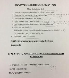
  1. Submit one soft copy  CD to PMD & P TD
  2. Submit one soft copy  HARD DISC to CSD
  3. Updated point list to SCADA
  4. All documents submit through proper submittal with Delivery Note


Thursday, March 30, 2017

TRANSFORMER & REACTOR STABILITY CALCULATIONS

TRANSFORMER STABILITY CALCULATION

67MVA TRANSFORMER


502 MVA TRANSFORMER 


 180MVAR REACTOR STABILITY 


1. Use the sensitive clam meter to easure the reactor current 
2. Concidor the vector group of the transformer and reactor for curculating the current 
 3. Both side star star current curculating will not happend 
4. So open any one pole of reactor CB and disable the PD to avaid the trip
5. Now the unbalance current will flow throgh the Reactor neutral. 
6. Short the NGR to make the current flow in the neutral CT. 


.


About Me

My photo
THIS IS SIVA T&C ENGINEER IN NCC LTD - SAUDI.