Friday, January 27, 2012

TRANSFORMER BUCHHOLZ RELAY


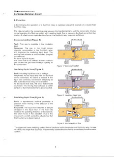
Transformer buchholz relay Test buttons

34.5 KV SWG INSIDE BUS ARANGMENT

DIODE TB


Diode NO : 4006 (6 Amps rating)

KITZ 102 FOR MICOM REALAY COMMUNICATION


1.KITZ 102 Converter.(125V DC)

2.RS 232 - 9Pin Male Jack

3.25Pin to 9Pin Converter Cable.( Normaly It'll come with KITZ102 Converter.If Not means this type cable need)

4.In the RS 232 - 9Pin male jack you've to use 4th&7th Pin for communication.

MCCB' s TESTING EQUIPMENT

Monday, January 23, 2012

ECO FEED

Consider Sub-1 & Sub-2. A fault is exits in the Sub-1 bus.
In this condition a line is energized by closing the other end Sub-2 Line breaker.
The Sub-1 bus is trying to energize by close the Line breaker. Minimum 50ms will take to close the CB poles and CB status contacts. During this operation the fault current will start to follow through the arec between CB poles.This fault current seance by Other end relay as Zone -2 faults and it will send a carrier to the Sub-1 relay with in 20 ms.Sub-1 relay will sense this fault current as reverse Zone -4 fault and it will not trip the won breaker.Sub-1 relay will receive the carrier and reply back to Sub-2 relay and conform two thinks ones Zone 4 reverse current and CB open.with in 20 ms this carrier will reach the the Sub -2 relay and relay will trip the breaker.

Monday, January 16, 2012

PD I STAGE RESET

1.The CB one or two Poles are fail to open or close the PD stage-I operate and open the breaker. If CB dose not open PD stage II will operate.Now PD stage-I trip command should reset.Otherwise The trip command continuously going to Trip Coil.

2.We can reset the PD stage-I relay in two ways 1.The PD stage-II contact can add serious with PD stage-I tripping circuit or serious with timer +ve. 2.PD stage-I Timer should be on delay pulse generator and it will give one pulse to PD stage-I tripping relay and not continuous pick-up command.

3.This method can be use in BF circuit also.

BATTERY TESTING

1.Don't short the battery bank +ve and -ve in same battery or total bank.

2.IF 2 volt battery after discharge test the voltage should be 1.75 v or as per data schedule.If less than this value battery should be change.

3.The individual can't test in the site level.Each cell as 2 volts and it can't drive more current and total discharge time will take more time.New replacing batteries should test with total batter bank.

4.The discharge test load current will calculate by Load Vs Time chat available in battery bank manual.
Tuesday, January 3, 2012

GIS GAS FILLING

The Gas monitor pressure Gauge used in GIS is Designed to show the reading as pressure readings convert to 20 Dec temperature.

When ever fill the gas in GIS connect one Digital Gauge parallel with Analog gauge which is show the reading with normal room temperature reference.

About Me

My photo
THIS IS SIVA T&C ENGINEER IN NCC LTD - SAUDI.